SAIL
The SAIL, or STEMnaut Atmosphere Independent Lander, was designed and built for the 2023-24 NASA Student Launch competition’s payload challenge. Its purpose was to deploy out of the rocket 400 feet above ground level, descend at human-survivable speeds, and land in a predetermined orientation without the use of a parachute or streamer.
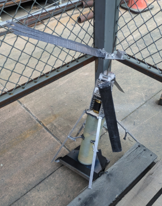
Folding within a 5.3” ID tube, the 15”-long rotor blades and 16” landing legs are spring hinge-actuated to autonomously extend themselves upon exiting the rocket. The two sets of rotor blades rotate opposite of each other utilizing a motor-powered coaxial gearing system. The following model and images delve deeper into the madness.
Components & Features
Rotor Blades

The SAIL rotor blades were constructed using 3D-printed CF-PC internal sections which were epoxied together and coated in unidirectional, axial-facing carbon fiber using an infusion molding process. They spanned a 2” chord and 15” length, following a basic NACA airfoil design. Intended to withstand ~500 lb. centripetal forces, they underwent Instron tensile testing and withstood 517 lbf, fracturing at the mounting holes.
Deployment Bay & Release Latch
To release the payload, a servo-actuated latch mechanism is secured to a deployment bay (5.3” ID tube) that nests inside the rocket. Hooked to the latch is a shock cord, which loops around an eye-bolt screwed to the payload. During the rocket’s descent, the deployment bay – separated by black powder charges and linked to the nose cone and neighboring bay by shock cord – is hung vertically for safe payload release. From there, a ground control signal is sent to actuate the servo, releasing the payload for descent.
Blade Mounting Assembly
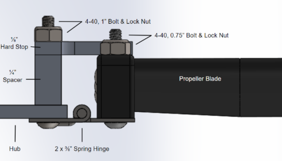
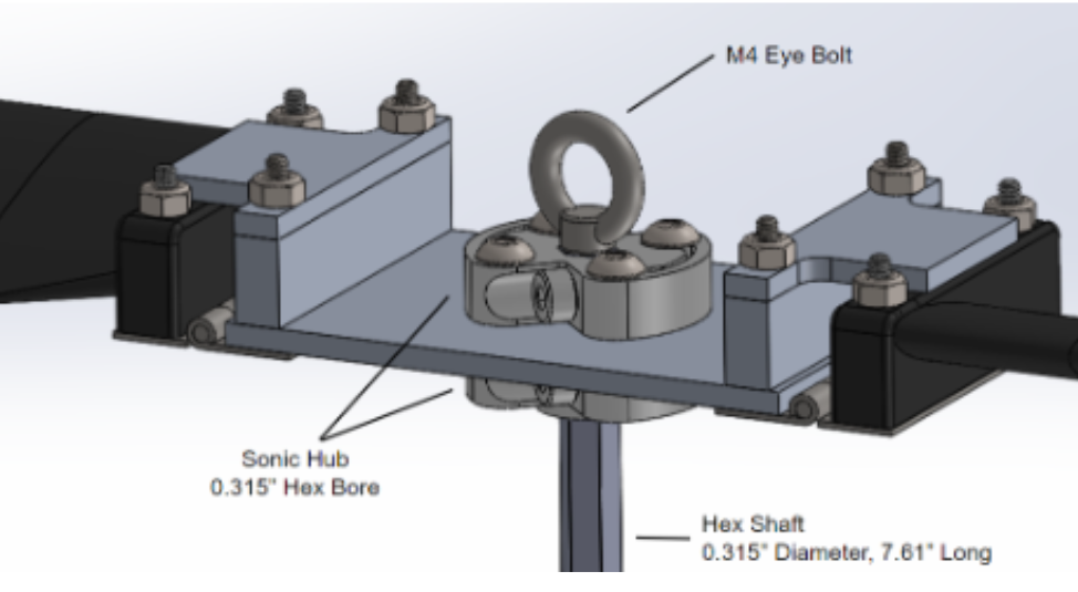
The rotor blades were mounted to spring hinges that connect to 3” dia. aluminum rotor hubs. These hinges allowed the rotor blades to fold within the rocket and extend once released, similar to the landing legs. Hardstops were implemented to keep the rotor blades in a horizontal position to prevent instability. The rotor hubs connect to the gearbox for coaxial rotation.
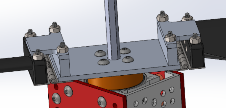
Gearbox
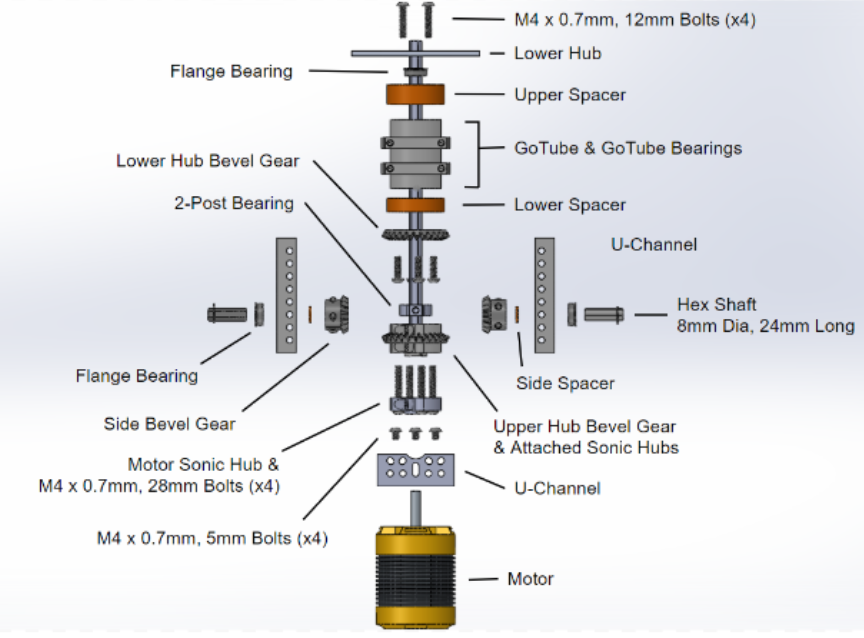

To coaxially rotate the rotor blades, a system of bevel gears were put in place. The motor shaft secures to the central hex shaft, spinning it in the same direction. This central shaft threads through the entire gearing system until it attaches to the upper rotor hub. It also attaches to the lower bevel gear, which spins a side bevel gear, rotating the upper bevel gear in the opposite direction. Attached to this upper bevel gear is a mounting tube that can attach to the lower rotor hub, thus spinning it in the opposite direction of the upper rotor hub! Bearings and 3D-printed spacers ensure stability of the system.
Landing Legs

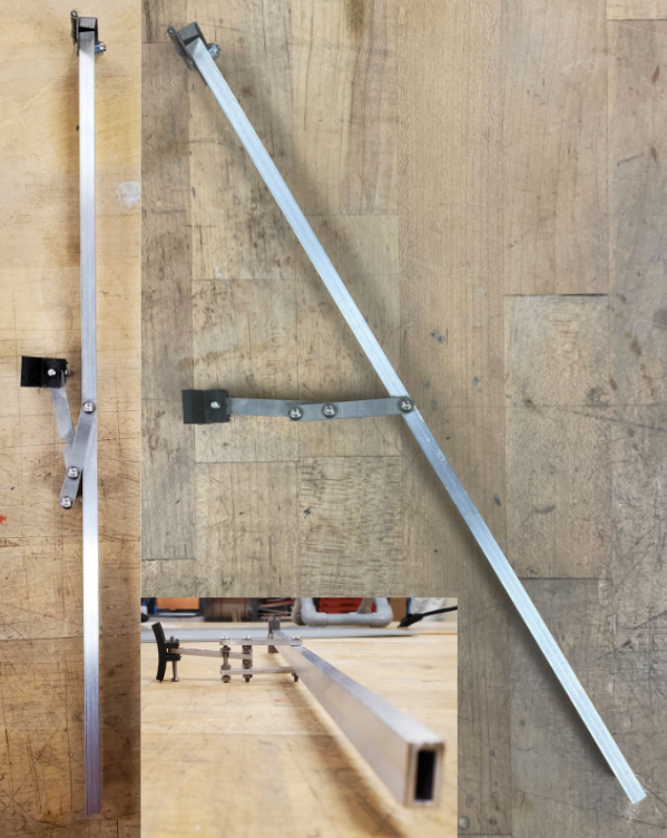
To ensure the payload lands in an upright orientation, four landing legs (official pronunciation “laegs”) deploy utilizing spring hinges and lock from stretching out further, giving a 15” dia. landing platform. They lock with a simple linkage system where a pin connecting two linkages is slotted into the other linkage upon being released.
Success?


Through literal blood, sweat, and fake tears, this payload was developed over the 2023-24 school year, beginning as a far-fetched dream of auto-rotation. We quickly discovered that it wasn’t feasible (proved wrong by another team!) and went the “safer” route of powered rotation.
The CAD model was designed over 2 months until a payload mass simulator was launched on the subscale rocket. The recovery system was deemed unsafe due to shock cord entanglement, thus leading to the deployment bay design. This caused a change of payload design, requiring its outer diameter to be 5.3” from the initial 6”! It reduced the rotor blade count from 8 to 4 and the landing leg length by ~5”. It also shrunk the electronics bay OD by an inch, leading to tight packaging.
By January, the design was mostly finalized and parts were beginning to ship for construction. Major delays were caused by the electronics bay tube reaching us in March, much later than expected. During this time, however, the gearbox was tested and improved as we discovered shortcomings of the design. Eventually, we had a fully functioning payload that same month, allowing us to test thrust metrics. We achieved ~7.8 lbs. of thrust, which was nearly sufficient for human-survivable descent, until the off-the-shelf rotor blade hinges unraveled, destroying the rotor blades. After 3 days of blade manufacturing, the payload was ready for testing again. Electrical issues cropped up, leading to an accidental ESC frying session, and ultimately ending our hopes of a fully operational payload launch due to time constraints. However, we were still able to drop the payload at Huntsville under parachute with the blade assembly and gearbox removed.
Solidworks CAD
CAD Instructions
Basics
- Download the file
- Extract .zip file contents
- Open the “Payload ‘24 v2” folder
- Open the “Important Assemblies” folder
- For a partially limited full assembly view, see the Full Assembly section
- To get full control of the appendages and coaxial rotation, see the Sub-Assemblies section
Full Assembly
- Open “Full Assembly.SLDASM”
- NOTE: this is a LARGE assembly!
- In the CommandManager, click on “Assembly” on the far left
- Click “Large Assembly Settings”
- For improved visuals, you can locate the small, blue/white 3D cube – below the CommandManager – titled, “Display Style.” Select the topmost option, “Shaded with Edges”
- To see the appendages fold within the 5.3” ID deployment bay
- Left click the “Coaxial Propeller System” sub-assembly
- At the top of the pop up, click on the listing with the title, “Deployed State”
- Click the third option, “Folded State”
- Click the green checkmark to the right of this listing
- Repeat for the “Electronics and Legs” sub-assembly
Sub-Assemblies
- Coaxial Rotation
- Open “Coaxial Propeller System.SLDASM”
- Simply click on one of the rotors, the external clamping collars, or any part of the gearbox and move your cursor!
- To see the internal gearbox move, ctrl + left click faces of any view-blocking external structures (red and light grey)
- Right click one of the selected faces
- At the top of the pop up, select the 5th button titled, “Change Transparency”
- This can be undone by ctrl + z
- Rotor Blade Folding
- Simply click on any rotor blade and drag down!
- Landing Leg Folding
- Open “Electronics and Legs.SLDASM”
- Simply click on any leg or linkage and drag down!
- You may have to alter your viewing point for optimal control
- To see the electronics and STEMnauts (lil ducks), you can change the transparency of the green tube
