Rover
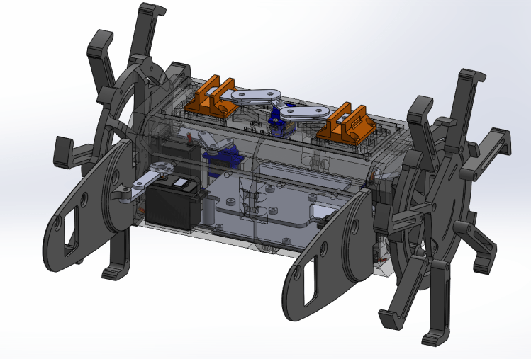
In Spring 2023, the WolfWorks Experimental team designed, built, tested, and flew a fully 3D-printed rover. Made out of CF-PETG material, the rover was designed to drive on the farm we launch at in Grantsboro, NC. It contains 2 continuous servo motors, 5 positional servos, an ultrasonic sensor, buck converters, an Arduino Uno, and a LiPo battery. The body was designed to just fit inside a 6″ diameter body tube to maximize internal space for electronics, with wheels that can expand an additional 3″ dia. for easier traversal of rough terrain. It has a parachute release mechanism to avoid parachute entanglement as well as driving stabilizers. It is named “Subway Spinning Vehicle” because it is a foot long (not sponsored).
Components & Features
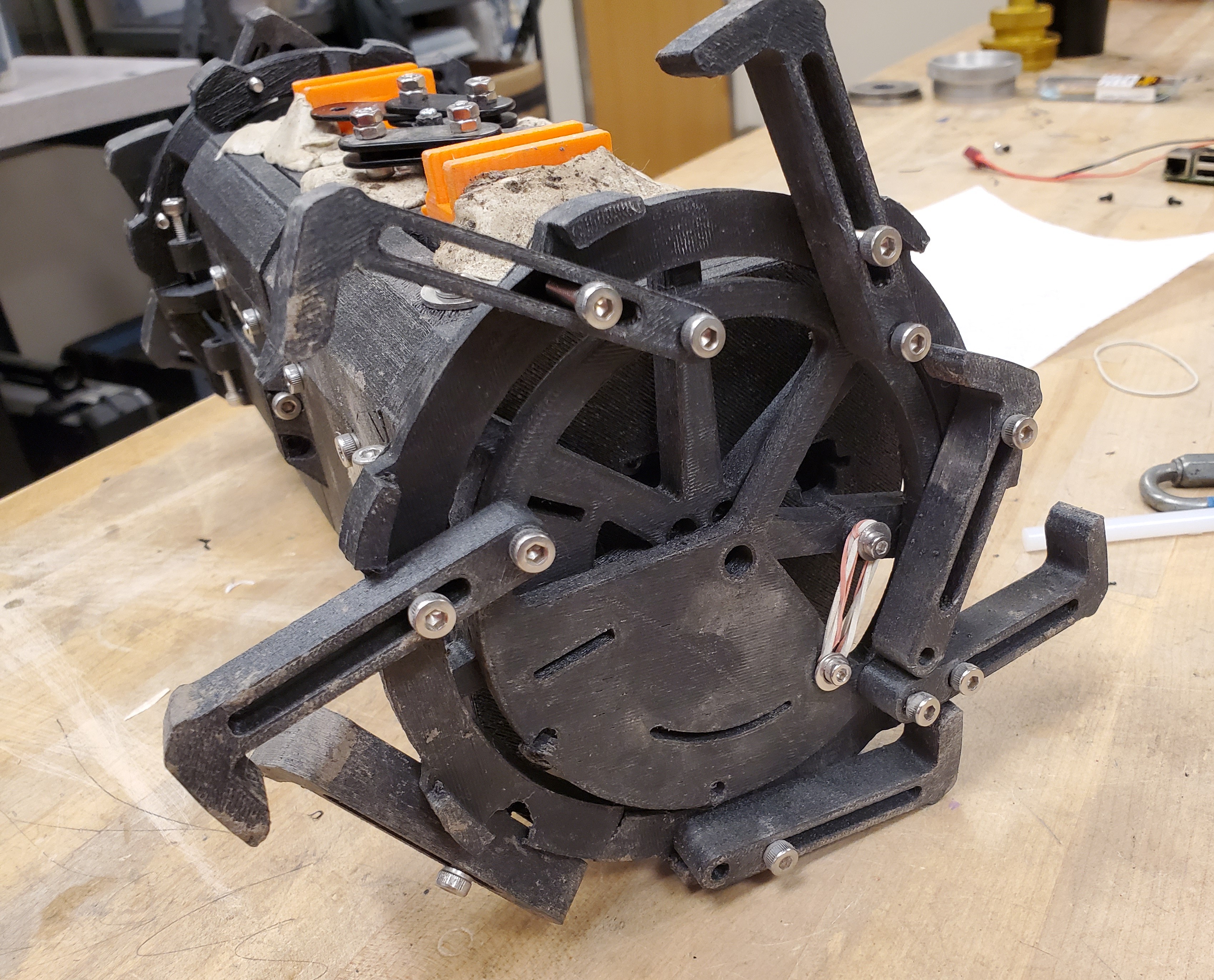
Expandable Wheels
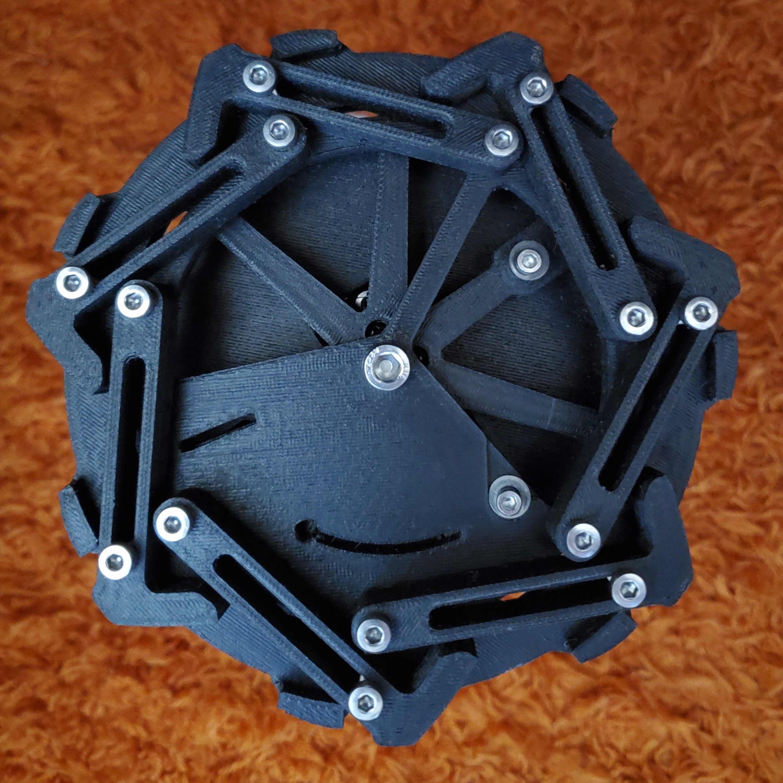
Continuous servo motors control each wheel’s speed and supply enough torque to drive on rough terrain. The wheels also expand from a 6″ to 9″ diameter to ease the traversal. Each wheel is spring-taut and locked by linkages, retracted using a positional servo, thus releasing the wheel spokes. This is set to happen ~20 seconds after exiting the rocket where an ultrasonic sensor notifies the system of its release. This is because the spring is not strong enough to deploy the spokes on ground.
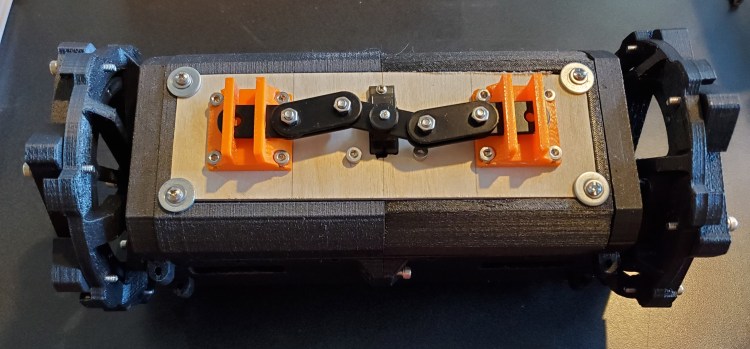
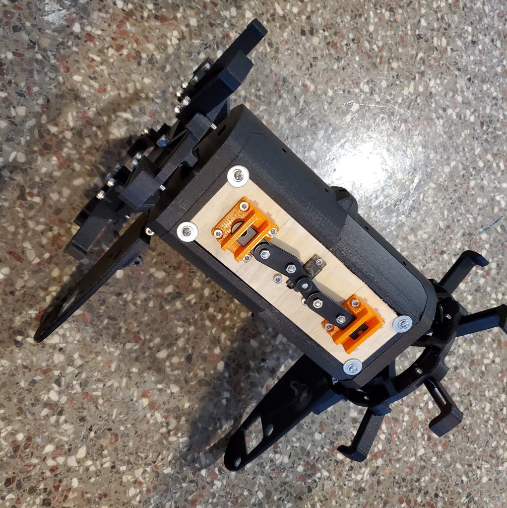
Parachute Release Mechanism
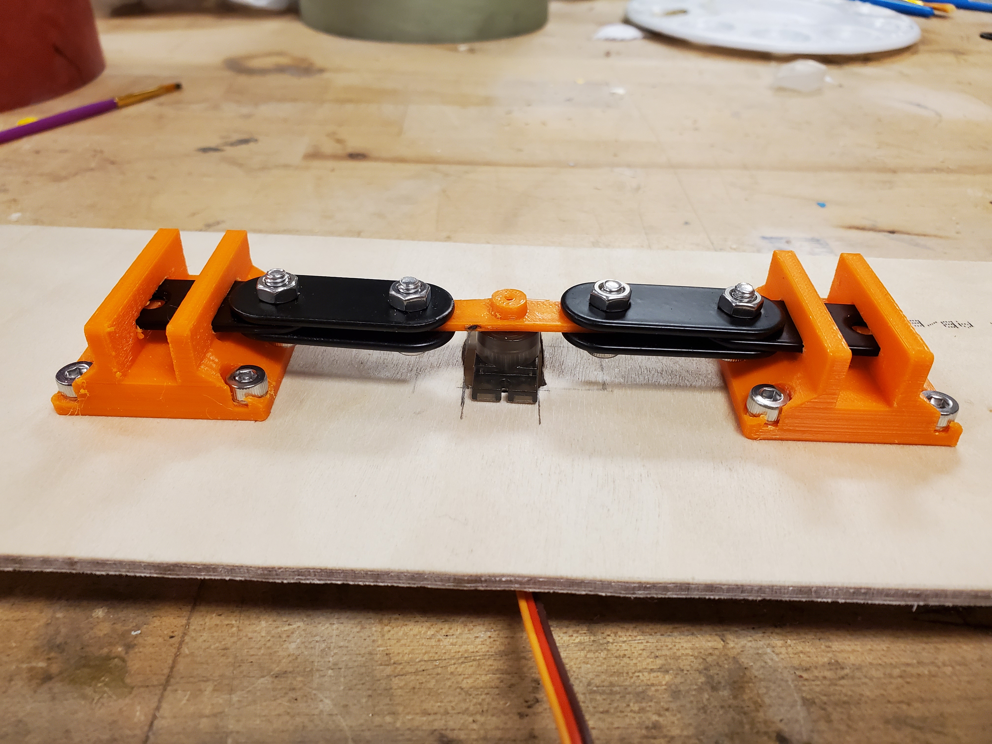
Once the rover lands, the parachute can easily entangle itself with the wheel spokes, so a parachute release mechanism was devised. It is simply controlled by one positional servo, where its horn extends in opposite directions, connecting to a set of linkages. These linkages, both of which are looped by shock cord, fit inside mounts. The middle of this shock cord is tied to the parachute cord connection point. Once the servo horn rotates, the linkages pull out of the mounts linearly to release the parachute.
Stabilizers
Two large, rounded “skis” are folded to the side of the rover until landing at which point they are extended using positional servos and linkages. Since the rover body is “floating” off the ground, the wheel motors would simply spin it in place. Thus, stabilizers are needed to counteract this torque force, allowing it to drive. They also keep the rover aligned.
Success?
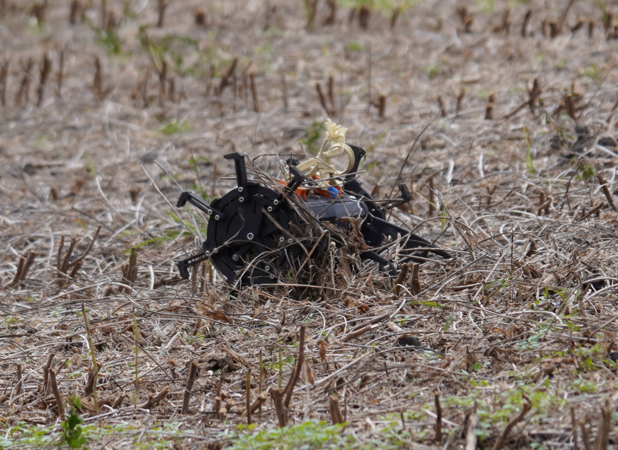


Within 3 months, this rover and the recovery system were designed, built, and launched. Unfortunately, the recovery system failed, resulting in shock cord and parachute cord entanglement, but the rover was, thankfully, rather unscathed. The rover was tested on the farm field, however, yielding great success.
Jumping forward to our Interest Launch at the beginning of the next school year, a new recovery system was devised. Sadly, the main parachute black powder separation struggled, releasing the rover at a higher descent velocity than anticipated and ripping off the parachute mounts cleanly. The good news? We got a cool meme out of it.
Solidworks CAD
CAD Instructions
- Download the file
- Extract .zip file contents
- Open the “rover” folder
- Open the “Rover Assembly” folder
- Open the “Rover” assembly file
